Goal
Explain in simple terms how to wire momentary buttons, momentary toggle's & CTS rotary encoders on a sim racing button plate OR sim racing wheel.
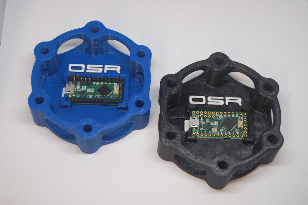
The OSR Micro is a complete USB-based micro controller development system, in a very small footprint, capable of implementing many types of projects. All programming is done via the USB port & arduino development environment.
When you buy a OSR Micro circuit, it comes pre-programmed ready for wiring and is recognized by a PC as a standard USB device and will work with all sim racing titles, such as iRacing, Project Cars, Assetto Corsa, Dirt Rally, Codemasters F1, etc.
OSR Micro Pin out
Our pre-loaded OSR Micro supports 26 momentary buttons/toggles, Upto 6 CTS encoders(with 14 button). We can also support a "Funky switch" with up to 19 Buttons and upto 2 additional CTS Encoders leaving 15 Buttons.
All the buttons & encoders can be daisy chained together to us 1 ground. Each button has it's own pin. Note matrix wiring & diodes are NOT required with any OSR Micro circuit.**Specific wiring for Funky**
IF you don't want to use rotary encoders the OSR Micro can support up to momentary 26 buttons.
Momentary Buttons
Buttons come in many different visual styles & electronic support, below are just a few.


In sim racing we only "typically" use the type which are momentary "Normally Open" which means no electricity pass through the button until it's pressed (closed circuit) and when it's released the circuit again is "open" to prevent current from passing through.
In a normal car we use buttons or switches to typically "Turn On" headlights or wipers, these are rarely supported sim racing software. In a typical sim racing title we normally use a momentary button to turn lights On & then press the button again to turn them off.

In sim racing we only "need" two terminals, if your momentary button has three terminals you will need to find which terminal is "normally open" & which terminal is "normally closed. It is very simple test using a "cheap" circuit tester OR a battery & a blub. Connect the ground wire to the center pin & then try to pass a current to one of the terminals and note if the "bulb" lights up before you press the button. IF it does then thats the Normally Closed terminal, if not press the button and the bulb should light up, you have now identified to "Normally Open" terminal.
Rotary Encoder (CTS)

Rotary encoders are typically used to increase or decrease values in sim racing software such as brake bias. In very simple terms when you turn the knob the software is sent multiple button signals based on the degrees turned.
Wiring is very similar to momentary button, BUT the circuit connections are always consecutive ODD/EVEN pins. e.g.: Connect your encoder on PIN5/PIN6, NOT Pin4/Pin5.

How to solder...
- Place the soldering iron in its stand and plug it in.
- Wait for the soldering iron to heat up.
- Moisten the sponge.

- Wipe the tip of the iron on the damp sponge, to clean the tip....
- Melt a little solder on the tip of the iron. ...
- The tip of the soldering iron should be a shiny silver color.


- Strip about 1/4" of the sheathing from two cables
- Twist the both ends together
- The soldering iron needs to be very hot...
- Now hold the tip on the two wires which you just twisted together for about 2>5 seconds depending on the power of your soldering iron.
- Now touch the solder on to the wire, (NOT the soldering tip), and you should see the solder flow around the wire like liquid. Add enough solder to fully cover all the wire.
- Remove the soldering iron and allow the solder to cool.

It's that simple, now just cut the joined cables to length, add a short section of heat shrink & apply a little heat so the heat shrink tube shrinks around the wire.
Soldering on a circuit board takes a little more care and attention, but it's still very doable.

- Strip about 1/4" of the sheathing from one of the cables
- Twist the loose wires together

- The soldering iron needs to be very hot...
- Now hold the soldering tip on the wire you just twisted together for about 1>3 seconds depending on the power of your soldering iron. The single wire being "tinned", so things heated up a lot faster.
- Now touch the solder on to the wire, (NOT the soldering tip), and you should see the solder flow around the wire like liquid. This time just add enough solder to lightly tin the wire end. Allow the wire end to cool.
- Push the "tinned" wire end through the appropriate hole in the OSR circuit.
- When soldering leads into circuit boards you want to heat the metal contact on the board and the lead itself. Applying too much heat can damage the circuit board or even your components. The surfaces being joined in this application were much smaller than the twisted wire, so things heated up a lot faster.
- Touch the tip of the iron to the crack between the lead and the metal pad on the circuit board. After waiting a couple of seconds, dip the tip of the solder into the joint and placed a very small amount of solder at the connection - no more than the head of a pin or so.
- Once the solder pooled a bit and soaked into the joint I removed the solder wire and then the iron. I remove the solder a second or two before I remove the iron so that the tip of the solder doesn't get stuck to the joint. The solder begins to harden as soon as you remove the iron.
- Using the proper amount of solder is more important while soldering small components on a circuit board than when soldering wires. If you apply too much solder and it pools up outside of the metal pad, it can cause a short. Too little solder and your component won't make a good connection with the circuit board and might not work the way you want it to. When you've got the right amount of solder it looks like a small ant hill that forms right at the base of the lead and the circuit board.

Wiring Typical Momentary Buttons & Rotary Encoders
